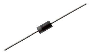
Through-hole fixed inductor featuring 680nH inductance with a 10% tolerance. This molded wirewound component operates with a maximum DC current of 495mA and a DC resistance of 600mΩ. Designed with a phenolic core and body, it offers a Q factor of 28 at 25MHz and a self-resonant frequency of 275MHz. The axial package measures 6.6mm in length and 2.67mm in diameter, with a lead diameter of 0.546mm. Operating temperature range is -55°C to 125°C.
PackageAxial
MountingThrough Hole
Inductance680nH
Quick Jump:
Technical Specifications
Vishay IM02EBR68K technical specifications.
General
| Body Material | Phenolic |
| Package/Case | Axial |
| Core Material | Phenolic |
| DC Current | 495mA |
| DC Resistance (DCR) | 600mR |
| Diameter | 2.67mm |
| Inductance | 680nH |
| Inductance Tolerance | 10% |
| Lead Diameter | 0.546mm |
| Lead/Base Style | Axial |
| Length | 6.6mm |
| Max DC Current | 495mA |
| Max Operating Temperature | 125°C |
| Military Standard | Not |
| Min Operating Temperature | -55°C |
| Mount | Through Hole |
| Package Quantity | 200 |
| Packaging | Bulk |
| Q Factor | 28 |
| Radiation Hardening | No |
| Reach SVHC Compliant | Unknown |
| RoHS Compliant | Yes |
| Self Resonant Frequency | 275MHz |
| Series | IM |
| Shielding | Unshielded |
| Termination | Axial |
| Test Frequency | 25MHz |
| Tolerance | 10% |
| Weight | 0.010582oz |
Compliance
| RoHS | Compliant |
Datasheet
Vishay IM02EBR68K Datasheet
Download the complete datasheet for Vishay IM02EBR68K to view detailed technical specifications.
This datasheet cannot be embedded due to technical restrictions.